Willkommen zur German Website
Wir haben festgestellt, dass Sie möglicherweise die Global Seite bevorzugen. Bitte verwenden Sie die obige Auswahl, um Ihre Sprache bei Bedarf zu ändern.
Go to Global
- Produkte
- Lösungen
- Support
- Services
- Über uns
Willkommen zur German Website
Wir haben festgestellt, dass Sie möglicherweise die Global Seite bevorzugen. Bitte verwenden Sie die obige Auswahl, um Ihre Sprache bei Bedarf zu ändern.
Products which support digital communications allow a computer system to read process data, display it on the screen and to store it away. The link may also be configured to write values to the equipment, thus providing a flexible Machine Interface. Communications links may also be used to allow one controller to pass parameters such as setpoints directly to other controllers, allowing more complex control strategies to be implemented.
Digital Communications is preferable to analogue communications (e.g. 0-5V) because:

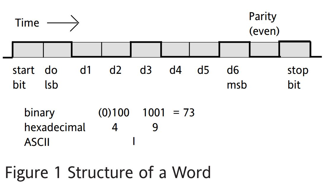
The data to be transmitted is broken up into small pieces known as Words which are then transmitted as a succession of changes of state. Each state, referred to as a Bit, has the same time duration. The number of bits sent per second is known as the Baud Rate. There are any ways in which the message content can be broken down into words and in order to be able to re-create the original message it is necessary for the receiving equipment to know how this was done and the rate at which the bits are being sent. The diagram shows several different ways in which the bits forming a word can be interpreted. This interpretation is described by the term “Protocol”.
The word Protocol is used to describe more than one element of the communications structure.
The wiring is covered by a number of recognised standards and the ones used on Eurotherm equipment are:
RS232 +/-12 volts nominal (3V min,15Vmax) 3 Wires used, TRANSMIT (Tx), RECEIVE (Rx) and COMMON
This can only be used with a single device at each end of the wiring and is thus a One-to-One link


RS422 Differential Mode signalling using two pairs of wires, one pair in each direction +/- 200mV signal required at the receivers. Signalling levels at the transmitter of 0 and 5Volts Permits communication from one “master” device to many “slave” devices.
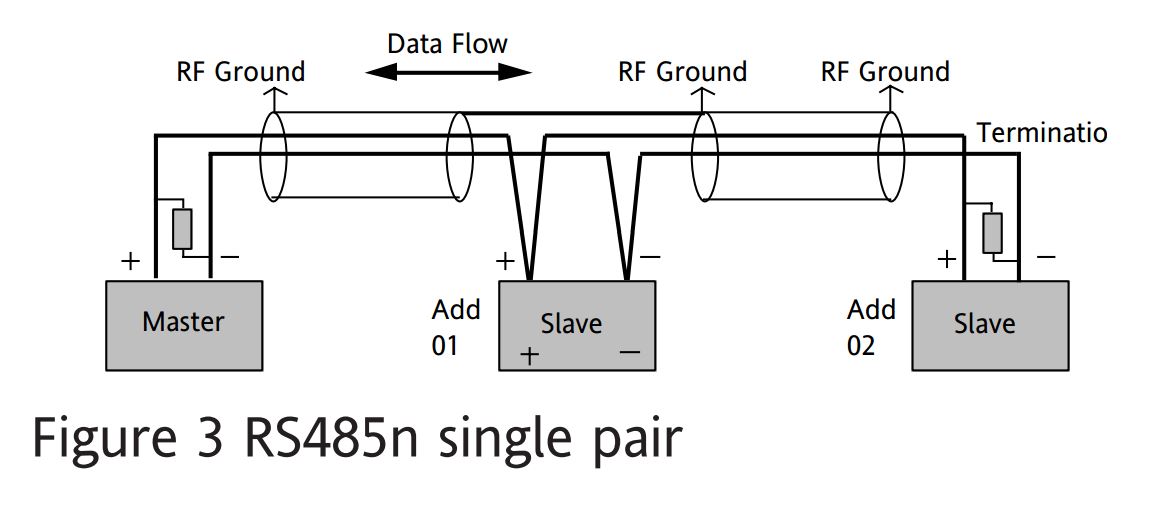
RS485 Differential Mode signalling using either one or two pairs of wires +/- 200mV signal required at the receivers. Signalling levels at the transmitter of 0 and 5Volts It is apparent that there are similarities between RS422 and RS485. They are not, however, identical and the differences are important:
When used with two separate wire pairs, RS485 can thus be seen as a higher capability version of RS422 . When used with only a single pair of wires there must be co-operation between instruments at each end of the link in order to ensure that both ends do not try to use the wires at the same time. The equipment must be designed to operate in this way.
Instruments designed for two pairs of wires will not communicate correctly on one pair. In using RS485 communications all instruments in the link must be designed for the same wiring arrangement.
Profibus communications are supported by a number of products from Eurotherm. This ‘fieldbus’ system allows very high speed digital communications using an enhanced RS485 wiring technology, and has become a de facto standard in factory.
DeviceNet is a cost-effective communications link designed to replace hardwired I/O interconnection between industrial devices.